Created Tuesday 14 November 2023
Configuring MCU
- Set MCU debug / clock options
- Add some GPIO output for LED output (we will togle it when MCU receives 0x01)
- Enable UART
- Enable DMA TX and RX channels
- Set RX channel mode to circular
- Enable UART global interrupt
- Generate code (ALT+K)
Adding library
- Copy uart.c and uart.h to core/src folder of your project (the same directory as main.c)
- Open uart.h, uncomment #define STM32G0 or #define STM32F0 depending on your MCU
- Add includes to /* USER CODE BEGIN Includes */:
- #include "uart.h"
- #include "math.h"
- Add code to /* USER CODE BEGIN PV */:
- #define UART_BUFFER_SIZE 128
- #define TEMP_BUFFER_SIZE 100
- __IO uint8_t uartBuffer[UART_BUFFER_SIZE];
- __IO uint8_t tempBuffer[TEMP_BUFFER_SIZE];
- Add code right before /* USER CODE END 2 */:
- COM_Init(0, &huart1, (uint8_t *) &uartBuffer, UART_BUFFER_SIZE, 100);
- float floatTemp=-60.3; // -60.3 Deg C
- Add code to while(1) loop:
uint8_t header;
uint8_t length;

if (COM_ReadFast((uint8_t *)&header,1)) switch(header)
{
	case 0x01:
	{
		uint8_t answer=0x55;
		COM_Write((uint8_t *)&answer,1);

		HAL_GPIO_TogglePin(GPIOB, GPIO_PIN_0);

		break; // command 0x01
	}

	case 0x02:
	{
		int32_t intTemp=round(floatTemp*1000);
		COM_Write((uint8_t *)&intTemp,4);
		break; // command 0x02
	}

	case 0x03:
	{
		COM_Read((uint8_t *)&length,1);
		COM_Read((uint8_t *)&tempBuffer,length);
		COM_Write((uint8_t *)&tempBuffer,length);
	 	break; // command 0x03
	}

}
Testing communication
- Ensure that STM32 and terminal speeds are the same, e.g. 921600bps
- Send 0x01 (hexadecimal), our firmware should answer 0x55
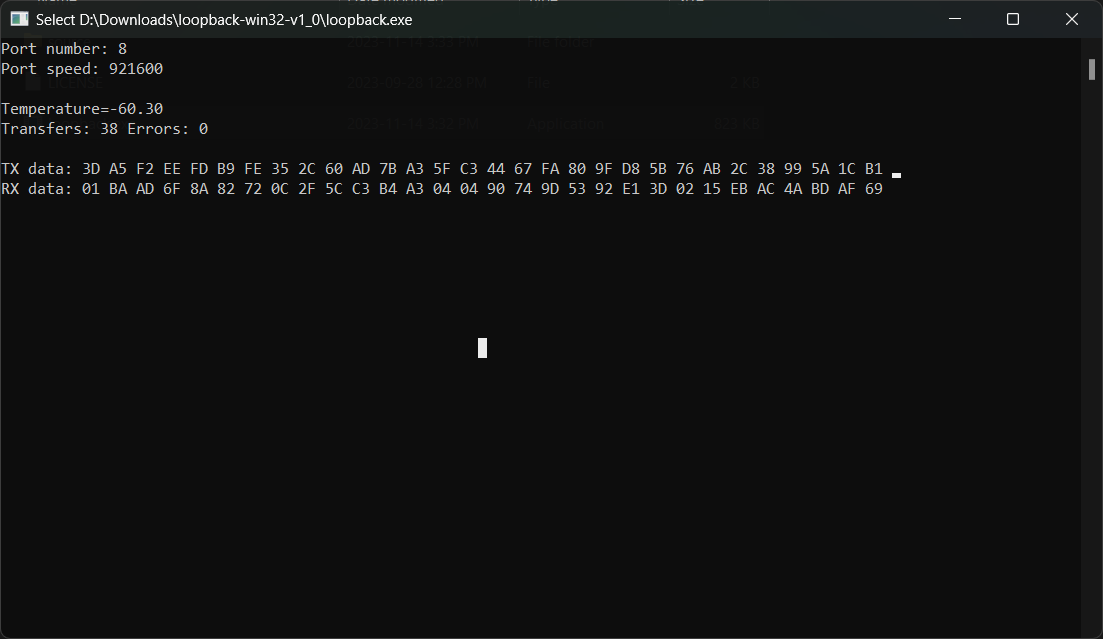
- Run loopback.exe program (can be downloaded here)
